Product Information
Solutions
Technical Information
Motor Sizing
Downloads
Virtual Showroom
Contact Us
Brushless DC Motors & Gear Motors > Technology > Calculating Stopping Accuracy of Brushless DC Motors
Calculating Stopping Accuracy of Brushless DC Motors
Stepper motors and servo motors with excellent stopping accuracy are commonly used when performing high-precision positioning operation. However, depending on usage conditions, brushless DC motors can stop with an overrun of several mm, with simple hall effect sensors used for speed control feedback. This paper explains this overrun, how to calculate stopping accuracy using overrun characteristics (typical value) of brushless DC motors, and two methods to improve stopping accuracy.
What is Stopping Accuracy?
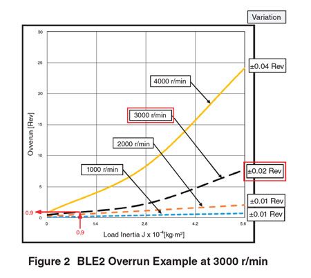
Stop accuracy refers to "error of actual stop position with respect to target position". Most of this error is due to "overrun’" characteristics of the motor. In addition to "overrun", a slight "variation" can occur. In mathematical terms, "stop accuracy = overrun + variation". By comparison, "variation" is very small. An example is shown in Figure 2.
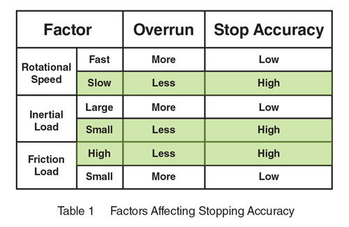
There are three main factors that affect stopping accuracy, and in the case of the highlighted cells in Table 1 below, "overrun" can be minimized. Pay attention to the rotational speed, inertial load and friction load, and how they affect the overrun and stop accuracy of the brushless motor.
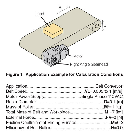
Application Example
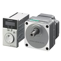
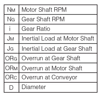
For the requirements given for the conveyor application above, it was determined that a 120W brushless motor and a gearhead with reduction ratio of 15:1 would be able to move the inertial load of 200 x 10-4 kg•m² in the required speed range. A system consisting of a BLM5120HPK-5H15S brushless motor, a BLE2D120-A dedicated driver, and a CC005HBLF motor cable from our BLE2 Series was recommended.
1. How to Calculate Stopping Accuracy:
Motor Speed (NM) = 3000 r / min
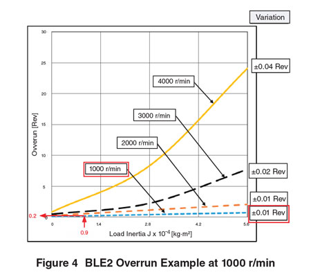
Use the overrun characteristics of the 120W BLE2 Series in Figure 2 under the following conditions:
1) Conversion of Motor Shaft
Since the graph below is the value of the motor alone, convert the rotational speed and inertial load of the gear shaft obtained by the selection calculation to the motor shaft.
①Motor shaft rotation speed
![]()
Use the curve of black dashed line of 3000 r / min to approximate.
②Motor shaft inertial load
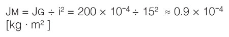
③When reading the overrun (vertical axis) value from the motor axis overrun ① (black dashed curve) and ② (horizontal axis), it is found that it is about 0.9 ± 0.2 [Rev].
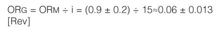
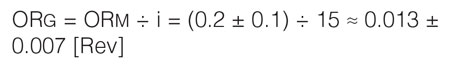
2) Conversion of Gear Shaft
Convert the overrun obtained in 1) to the gear axis.
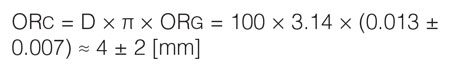
3) Conversion of Conveyor Belt
Convert the overrun obtained in 2) to the belt conveyor axis.
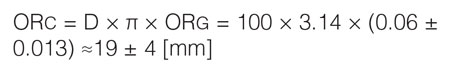
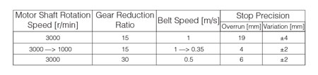
From the equations, it can be inferred that the overrun of the belt conveyor is 19 mm and the variation is ± 4 mm.
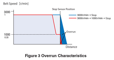
2-1. Improvement of Stopping Accuracy:
Deceleration & Stop Motor Speed
(NM = 3000 r / min to 1000 r / min to stop)
As you can see from the overrun characteristics in table 1, the overrun becomes smaller as the rotation speed decreases.
Here, we calculate the overrun when stopping after decelerating.
Calculate by the same procedure as 1. How to Calculate Stopping Accuracy. Reading overrun (vertical axis) from 1000 r / min (curve with blue broken line) and 0.9 × 10⁻⁴ [kg · m 2 ] (horizontal axis) shows that it is about 0.2 ± 0.1 [Rev]
Convert this value to the gear axis.
Finally convert to belt conveyor axis.
From the above, it can be inferred that the overrun is 4 mm and the variation is about ± 2 mm.
2-2. Improvement of Stopping Accuracy:
Increase Gear Reduction Ratio (i= 15→30)
As mentioned, the overrun of the gear shaft is the value of the motor shaft divided by the gear reduction ratio. Therefore, overrun can be suppressed by increasing the reduction ratio.
Here, we calculate the overrun when increasing the reduction gear ratio. (In this case, the speed of the belt will also halve to Max 0.5 m / s.)
1) Conversion of Motor Shaft
①To comply with the same conditions of the motor shaft rotation speed in 1. Calculate Stopping Accuracy, use the stopping accuracy calculation: NM = 3000 r / min", use the black dashed curve of 3000 r / min.
②Motor shaft inertial load
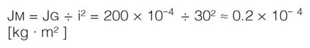
③When reading the value of overrun (vertical axis) from the motor axis overrun ① (black dashed curve) and ② (horizontal axis), it is about 0.6 ± 0.2 [Rev].
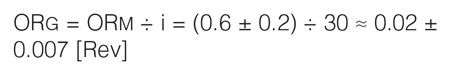
2) Conversion of Gear Shaft
Convert the overrun obtained in 1) to the gear axis.
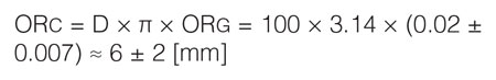
3) Conversion of Conveyor Belt
Convert the overrun obtained in 2) to the belt conveyor axis.
3. Conclusion
This document shows how to determine stop accuracy according to speed and inertial load as well other methods to effectively improve stopping accuracy of brushless motors. Our knowledgeable technical support engineers are available to help if any calculation assistance is needed.
Brushless DC Motors & Drivers