Product Information
Solutions
Technical Information
Motor Sizing
Downloads
Virtual Showroom
Contact Us
Brushless DC Motors > Technology > Features of the BMU Series
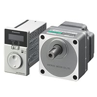
Features of the BMU Series Brushless DC Motor and Driver Speed Control Package
Brushless DC gear motors have been used as the driving source in a variety of equipment and devices. In recent years, the demand for smaller machines and lower energy costs has increased. Naturally, these demands have passed down to the motor as well. The BMU Series motor and driver package combines a brushless DC motor with a new driver for easy use. Compared with conventional motors, brushless DC motors are more compact, lighter in weight, and more energy efficient. In this paper, we describe the technology used to achieve the brushless DC motor's high efficiency and the features of the new BMU driver.
1. Introduction
Brushless DC gear motors have been used as the driving source for various types of equipment and devices. The demand for smaller machines with higher output power and lower energy costs has increased in recent years. The same expectation has been held for motors, but the additional demand for easy installation, connection, and operation has also increased. In order to meet such demands, a compact, light weight and high efficiency brushless DC motor was combined with an improved, easy to use driver. We introduce the BMU Series brushless DC motor and driver package (refer to Figure 1).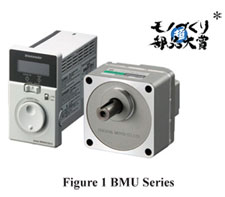
*The BMU Series received the Machinery Component Award at the "Super Creative Design and Manufacturing Awards" in 2013, in Japan.
2. Features of the BMU Series
The BMU Series motor and driver package consists of the redesigned brushless DC motor and the brushless driver with improved usability. The main features are indicated below:1. Compact, Light Weight and Resource Saving
New compact and light weight motor design from reduced materials in the motor.
2. Reduction of Power Consumption
Power consumption reduction is achieved with the BMU package product thanks to the improved efficiency of the brushless DC motor and driver
3. Improved Usability
Simple operations are possible with the improved driver
4. Additional New Functions
·Digital display
·Speed setting at 1 r/min interval
·Extended overload alarm detection time
·Load holding function
·Upper and lower speed limits settings
3. Compact, Light Weight and High Efficiency Technologies
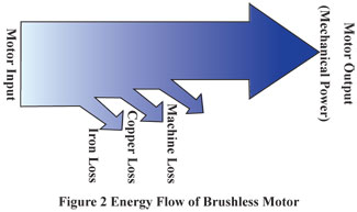
As shown in Figure 2, motor energy loss can be categorized into 3 different types; iron loss caused by magnetic steel sheets; copper loss occurring at the windings; and machine loss due to mechanical friction, etc. To achieve high efficiency, the key thing is reducing the energy loss. The loss reduction design of the new brushless DC motor will be explained in this chapter.
3.1. Iron Loss Reduction
Sintered neodymium magnets were used to achieve compact yet high output power. This caused iron losses to increase due to high magnetic flux density. It became necessary to reduce dysprosium, contributing to the reduction of rare earth material, which also increased the magnetic flux density, though not significantly.
Corresponding to the increase of the magnetic flux density, material, thickness, and configuration of the magnetic steel sheet were redesigned for optimal outcomes as detailed below:
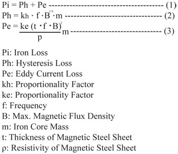
As shown in the equation (1), the amount of iron loss changes, based on hysteresis loss and eddy current loss.
Eddy current loss, as shown in the equation (3), is proportional to the square of the thickness (t) of a magnetic steel sheet. The thickness of a laminated magnetic steel sheet for the new brushless DC motor is 0.35 mm, thinner than the conventional motor of 0.5mm, resulting in the reduction of eddy current loss. Iron loss is proportional to iron core mass (m) which is the laminated body of a magnetic steel sheet. Therefore, iron loss was successfully reduced by the reduction of iron core mass.
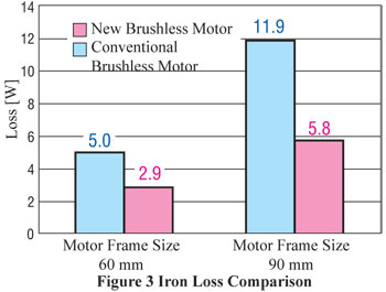
The thickness of the iron core was successfully reduced by almost half due to the optimized design of the magnet and stator. At the same time, this achieved reduced product weight, iron loss, as well as overall size. Figure 3 shows the comparison of iron loss at rated points.
3.2 Copper Loss Reduction
Copper loss can be measured with the following equation:
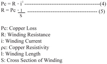
According to the equation (4), copper loss is determined by the resistance value of a winding as long as the winding current value remains the same. According to the equation (5), the key solution to reducing copper loss is to wind a thick and short wire.
Because the magnetic flux density of the magnet used in the new brushless DC motor increased, the configuration of the magnetic steel sheet needed to be changed by expanding the tooth width as shown in Figure 4.
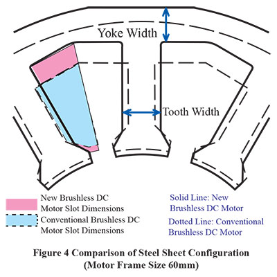
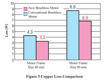
While the tooth width was widened, the slot dimensions were made smaller. To solve this issue, the slot depth was widened by employing a shell-type structure, which does not require a motor case. The design for the yoke width was achieved by improving the wiring method. As a result, the slot dimensions were increased by 37% compared to the conventional brushless DC motor. This resulted in the structure's ability to use the larger cross section winding (S) and hence reduces copper loss. Also, because the thickness of iron core was reduced by half, winding length (l) was shortened and resulted in the further copper loss reduction. Figure 5 shows the comparison of copper loss at rated points.
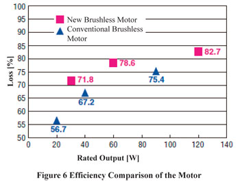
After updating the motor design, iron loss and copper loss (which account for the great majority of loss for motors) were reduced and greater efficiency of the motor and driver package was achieved, as shown in Figure 6.
3.3. Reduction of Motor and Gearhead Failure Point
Lately many motors have been using helical gears vs. spur gears to control gearhead noise (meshing sound). When a helical gear is used, the grease within the gearhead is scraped out due to the contortion of teeth grooves and occasionally the grease enters the inside of the motor. Commonly, an oil seal is placed at the motor output shaft to prevent this from happening. However, a high performance type oil seal needs to be used for a highly liquid grease to further reinforce the sealing performance (refer to Figure 7).
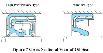
On the other hand, the more the sealing performance is reinforced, the bigger the load on the oil seal gets and this may severely impair the motor efficiency. The oil seal itself would need to become larger for better sealing performance and consequently, the motor would also need to be larger.
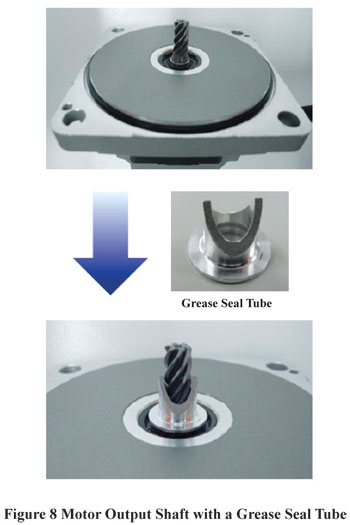
In order to avoid such situations, a simple yet very effective feature was developed. This feature not only shuts out the grease completely but also can be combined with the standard type oil seal (patent pending). The component used in this feature is called the grease seal tube. Figure 8 shows a grease seal tube and a mounting example of the tube used on the motor output shaft.
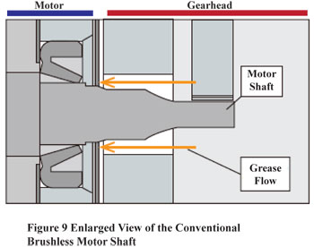
As shown in Figure 9, the conventional brushless DC motor used an oil seal only to stop the grease from seeping in. However, it was difficult to completely keep out the highly liquid grease.
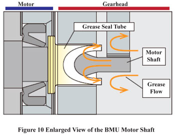
By placing a grease seal tube on the shaft as shown in Figure 10, most of the grease is bounced back even before it reaches the oil seal. This new feature prevents the grease from entering the motor.
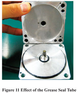
When removing the gearhead after the motor is used, it is clear that the grease has not entered the motor, as shown in Figure 11.
By applying the grease seal tube as an additional feature, the increase in load is minimized while keeping the motor compact and efficient.
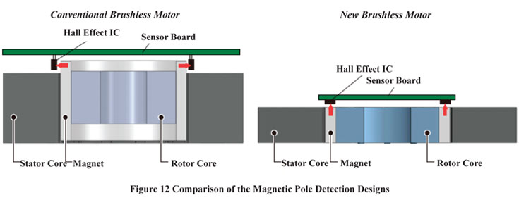
3.4. Changing the Magnetic Pole Detection Design to be Space Saving
A sensor board was installed at the same height as the coil end of the stator cover to save space (patent pending).
By changing the design, the Hall Effect IC can be mounted right above the magnet and therefore, there is no need to extend the magnet for the magnetic pole detection. The result is a more compact and lighter weight motor that also saves material and resources (refer to Figure 12).
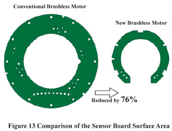
Along with the layout change of the sensor board, the wiring method was also reviewed so that the power line would not have to go through the sensor board. The board area was significantly reduced by 76% compared to the conventional brushless product (refer to Figure 13).
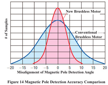
By changing the mounting method of the Hall Effect IC to the surface-mount type, high precision magnetic pole detection was achieved. With this change, the excitation timing is closer to the ideal value. Therefore, the amount of current put through the windings can be reduced resulting in higher efficiency.
Figure 14 shows the detection accuracy by the Hall Effect IC of the magnetic pole. The smaller the variation is between the magnetic pole detection angles, the higher the accuracy gets. By comparing to the variation distribution of the conventional brushless product, it is clear that the new brushless DC motor has a higher accuracy for the magnetic pole detection.
By reviewing the magnetic pole detection design, the size, weight and amount of resources used were all reduced.
4. Features of the BMU Series Driver
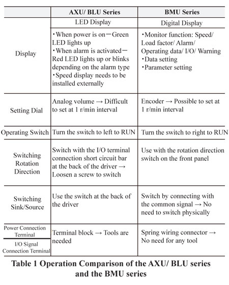
4.1. Comparison of the AXU/BLU Series and the BMU Series
4.1.1. Complete Design Change
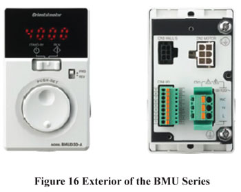
The design of the AXU/BLU Series driver was completely changed for the BMU Series by adding new functions and incorporating customer requests (refer to Figure 15, 16 and Table 1).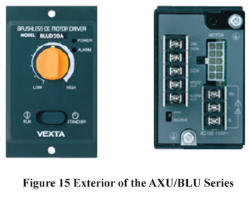
4.1.2. An Increase in Output Torque
The AXU/BLU Series motor output was suppressed due to restrictions on the driver. For the BMU Series, the heat dissipation design of the power component was reviewed since it is the biggest source of heat generation within the driver. Table 2 shows the comparison of the rated output, rated speed and speed control range of motors with the same frame size.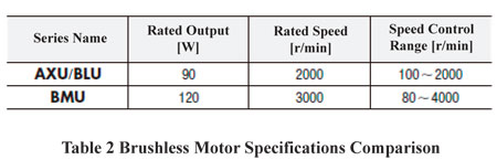
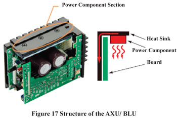
Regarding the structure of the AXU/BLU Series heat dissipation, the power component was placed right beneath the heat sink due to the parts layout (refer to Figure 17).
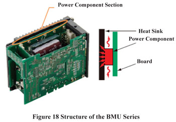
On the contrary, the BMU Series makes effective use of the heat sink by having the power component in the center. Furthermore, the structure dissipates the heat from the power component through the board in order to prevent the temperature inside the driver from rising (refer to Figure 18).
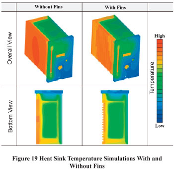
Also, heat simulations with fins and without fins were conducted during the heat sink design process. By applying fins, the surface area was increased, dissipating the heat effectively (refer to Figure 19).
Although the size is exactly the same as the AXU/BLU Series, the output has improved up to 120W by changing the structure.
4.2. Operational Performance Improvement
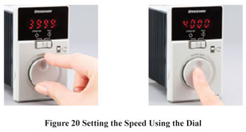
The main focus of the BMU Series was simplifying the use. Therefore, the functions and operational performance was reviewed by our engineers. The front panel was made to operate intuitively and details such as the direction of the STAND BY – RUN switch and the design of the data setting dial were important upgrades.The concavo-convex design of the setting dial makes it possible to operate with a fingertip or with gloves on. Refer to Figure 20 to view the panel's easy operation.
4.3. Digital Display
The digital display can monitor conditions such as speed, load factor, and alarms. Codes indicated on the display make it easier to determine the types of alarms and warnings.The speed display can show the speed of the gearhead output shaft as well as the transport speed of the conveyor.
The following is the equation of the parameter to display the transport speed of the conveyor:
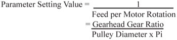
For the calculated parameter setting value, the transport speed of the conveyor is converted as follows:
![]()
An example is indicated below:
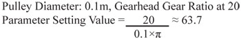
According to the calculation above, the parameter setting value is 63.7 and thus the gear ratio parameter is set at 63.7. With this setting, when the motor speed is at 1300 r/min, the transport speed of the conveyor is 20.4 m/min.
![]()
Accordingly, the display indicates "20.4".
4.4. New Function to Improve Usability
In order to improve usability, The BMU Series BLDC motor has additional new functions that are not available with conventional brushless DC motor packages.
1.Extended Overload Alarm Detection Time
For the conventional brushless DC motor packages, the time to activate the overload protection was 5 seconds for all products. However, there were many demands from customers to extend the time until the alarm was activated, for example, when the out of specification loads are applied during operations, which would trigger the alarm.
Improving the heat dissipation structure for the power component made it possible to extend the overload alarm detection time.
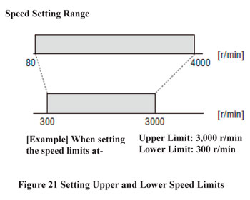
2.Setting of Upper and Lower Speed Limits
The speed control range is from 80 r/min to 4000 r/min in general, but depending on the specifications of the equipment, the upper and lower speed limits can be set. This function can prevent incorrect operations (refer to Figure 21).
3.Load Holding Function
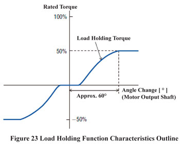
When the motor is stopped, holding torque, which is approximately 50% of the rated torque, is generated based on the change of the motor output shaft. This makes it possible for the motor to hold at a desired position.
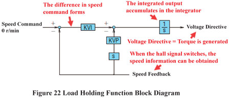
The principle of torque generation while the load is held is indicated in Figure 22. When a change occurs at the motor output shaft due to external forces while the motor is stopped, the hall signal switches automatically to obtain the speed information. Based on the detected speed information, the difference of the speed command is detected and the voltage directive is sent out from the integrator to generate enough torque to bring the speed down to 0 r/min.
This function differs from position control as it does not completely bring the shaft back to the original position. This can be used to simply hold the load when the angle of the motor output shaft is within the range of ±60° (refer to Figure 23). However, holding torque cannot be exerted when the power supply is cut off.
5. Product Introduction
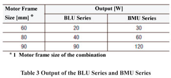
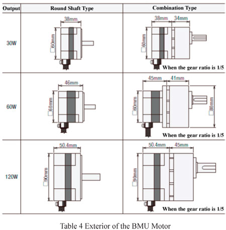
The BMU Series BLDC motor offers 3 output types at 30W, 60W and 120W. Also, 2 types of power supply voltage specifications are available; single-phase 100-120 VAC type and 200-240 VAC type and three-phase 200-240 VAC type. Compared to the BLU Series, the motor size is smaller and output has been further improved. Besides the round shaft type, the combination type with the parallel shaft gearhead is also available (refer to Table 3 and 4).
6. Summary
The BMU Series BLDC motor offers a redesigned motor and driver package which will play a prominent role in the future. This product not only downsizes the equipment but also saves power due to its high efficiency. The new technology applied to this product was recognized with the Machinery Component Award at at the "Super Creative Design and Manufacturing Awards" in Japan in 2013. The BMU Series will be expanding its product line in the near future. There is also a plan to develop a new driver to be combined with the BMU motor to further expand the product.
Brushless DC Gear Motors