Servo Motor Overview
Structure of Servo Motors
The servo motor has a rotation detector (encoder) mounted on the back shaft side of the motor to detect the position and speed of the rotor. This enables high resolution, high response positioning operation.
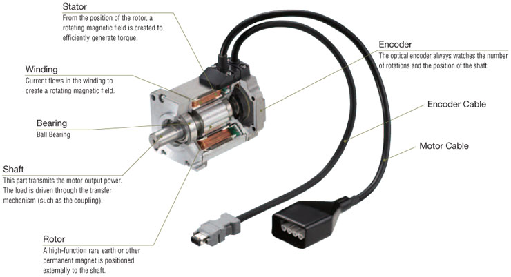
The following figure shows the construction of a standard servo motor.

1. Stator From the position of the rotor, a rotating magnetic field is created to efficiently generate torque.
2. Winding Current flows in the winding to create a rotating magnetic field.
3. Bearing Ball Bearing
4. Shaft This part transmits the motor output power. The load is driven through the transfer mechanism (such as the coupling).
5. Rotor A high-function rare earth or other permanent magnet is positioned externally to the shaft.
6. Encoder The optical encoder always watches the number of rotations and the position of the shaft.
7. Encoder Cable
8. Motor Cable
The encoder is a sensor for detecting the speed and position of the motor. Light from the light-emitting diode (LED) passes through a position detection pattern on the slit disk and is read by the light-receiving element. Dozens of photo transistors are integrated in the light-receiving element. All of the patterns for absolute position detection depends on the rotation angle of the encoder. The CPU is mounted on the encoder for analysis of the absolute position detection patterns. The current position data is transmitted to the servo driver via serial transmission.
Control Block Diagram of the Servo Motor
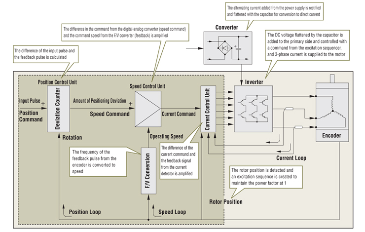
A pulse signal that is externally applied (when it is the pulse input type) and the rotation detected by the servo motor encoder, are counted and the difference (deviation) is outputted to the speed control unit. This counter is referred to as the deviation counter. During motor rotation, an accumulated pulse (positioning deviation) is generated in the deviation counter and is controlled so as to go to zero. The (position holding by servo control) function for holding the current position is achieved with a position loop (deviation counter).

The servo motor is composed of three elements: the motor, the encoder and the driver. The driver has the role of comparing the position command and the encoder position/speed information and controlling the drive current. The servo motor always detects the motor condition from the encoder position and speed information. If the motor should come to a standstill, the servo motor outputs an alarm signal to the controller for abnormality detection. The servo motor must adjust the control system parameters to match the rigidity of the mechanism and the load conditions, though in recent years, real time auto-tuning has made this adjustment easy.
