Basics of Stepper Motors
Every motor converts power. Electric motors convert electricity into motion. Stepper motors convert electricity into rotation. Not only does a stepper motor convert electrical power into rotation, but it can be very accurately controlled in terms of how far it will rotate and how fast.
Stepper motors are so named because each pulse of electricity turns the motor one step. Stepper motors are controlled by a driver, which sends the pulses into the motor causing it to turn. The number of pulses the motor turns is equal to the number of pulses fed into the driver. The motor will spin at a rate that is equal to the frequency of those same pulses.
Stepper motors are very easy to control. Most drivers are looking for 5 volt pulses which just so happen to be the voltage level of most integrated circuits. You merely need to design a circuit to output pulses or use one of ORIENTAL MOTOR's pulse generators.
One of the most remarkable features of stepper motors is their ability to position very accurately. This will be covered in depth later on. Stepper motors are not perfect, there are always some little inaccuracies. ORIENTAL MOTOR's standard stepper motors have an accuracy of ± 3 arc minutes (0.05°). The remarkable feature of steps motors, though, is that this error does not accumulate from step to step. When a standard stepper motor travels one step it will go 1.8° ± 0.05°. If the same motor travels one million steps, it will travel 1,800,000° ± 0.05°. The error does not accumulate.
Stepper motors can respond and accelerate quickly. They have low rotor inertia that can get up to speed quickly. For this reason stepper motors are ideal for short, quick moves.
Stepper Motor System
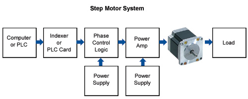
The diagram below shows a typical stepper motor based system. All of these parts must be present in one form or another. Each component's performance will have an effect on the others.
The first component is the computer or PLC. This is the brains behind the system. The computer not only control the stepper motor system but will also control the rest of the machine. It might raise an elevator or advance a conveyor. It can be as sophisticated as a PC or PLC or as simple as an operator push button.
The second portion is the indexer or PLC card. This tells the stepper motor what to do. It will output the correct number of pulses that motor will move and alters the frequency so the motor will accelerate, run at a speed, and then decelerate.
This could be a separate component like the ORIENTAL MOTOR SG8030 indexer or a pulse generator card that slides into a PLC. The form is immaterial, but it must be present for the motor to move.
The next four boxes make up the motor driver. The logic for phase control takes the pulses from the indexer and determines which phase of the motor should be energized. The phases must be energized in a particular sequence, and the logic for phase control takes care of this. The logic power supply is a low level supply that powers the ICs in the driver. It depends on the chip set or application design, but most logic supplies are in the 5 volt range. The motor power supply is the supply voltage to power the motor. This voltage level is usually in the 24 VDC range but can be much higher. Finally, the power amplifier is the transistor set that allows current to energize the phases. These are continuously turned on and off to move the motor through its correct sequence.
All of these components will instruct the motor to move the load. The load may be a lead screw, a disk, or a conveyor.
Types of Stepper Motors
There are currently three general types of stepper motors.
- Variable Reluctance (VR)
- Permanent Magnet (PM)
- Hybrid
ORIENTAL MOTOR only manufactures Hybrid stepper motors.
Variable reluctance step motors have teeth on the rotor and stator, but no magnet. Therefore it has no detent torque. The Permanent Magnet has a magnet for a rotor but no teeth. Usually, the PM magnet has crude step angles, but it does have detent torque.
Hybrid stepper motors combine the magnet from the permanent magnet and the teeth from the variable reluctance motors. The magnet is axially magnetized meaning in the diagram to the right the top half is a north pole and the bottom half is a south pole. On the magnet are two toothed rotor cups with 50 teeth. The two cups are displaced 3.6° so that if we look down the rotor between two teeth on the north pole cup, we would see one tooth on the south pole cup directly in the middle.
These motors are two phase construction, with 4 poles per phase. The poles 90° apart from one another make up each phase. Each phase is wound so that the pole 180° is the same polarity, while those 90° apart are the opposite polarity. If the current in that phase were reversed, so would the polarity. This means that we can make any stator pole either a north pole or a south pole.
There are 50 teeth on the rotor. The pitch between teeth is 7.2°. As the motor moves, some rotor teeth are out of alignment with the stator teeth by 3/4 a tooth pitch, 1/2 a tooth pitch, and 1/4 a tooth pitch. When the motor steps, it is going to take the easiest route, since 1/4 of 7.2° is 1.8°, the motor moves 1.8° each step.
Finally, torque and accuracy are dependent upon the pole (tooth) count. The greater the poles, the better the torque and accuracy. ORIENTAL MOTOR offers "High Resolution" stepper motors. These motors have half the tooth pitch of our standard motor. The rotor has 100 teeth so the angle between the teeth is 3.6°. When the motor moves 1/4 of a tooth pitch, it is moving 0.9°. The resolution of our "High Resolution" models is double that of the standard models, 400 steps per revolution versus 200 steps per revolution.
Smaller step angles mean lower vibration since we are not stepping as far with each step.
Structure
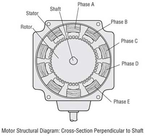
The figure below shows a cross-section of a 5-phase stepper motor. The stepper motor consists primarily of two parts: a stator and a rotor. The rotor in turn is made up of three components: rotor cup 1, rotor cup 2 and a permanent magnet. The rotor is magnetized in the axial direction so that, for example, if rotor cup 1 is polarized north, rotor cup 2 will be polarized south.
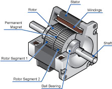
The stator has 10 magnetic poles with small teeth, each pole being provided a winding.
Each winding is connected to the winding of the opposite pole so that both poles are magnetized in the same polarity when current is sent through the pair of windings. (Running a current through a given winding magnetizes the opposing pair of poles in the same polarity, i.e. north or south.)
The opposing pair of poles constitutes one phase. Since there are 10 magnetic poles, or five phases, in this particular motor called a 5-phase stepper motor.
There are 50 teeth on the outer perimeter of each rotor, with the teeth of rotor cup 1 and rotor cup 2 being mechanically offset from each other by half a tooth pitch.
Speed-Torque
It is very important the you know how to read a speed-torque curve since it will tell us what a motor can and cannot do. Speed-torque curves represent a given motor and a given driver. Once the motor is running, its torque is dependent on the drive type and voltage. The same motor can have a very different speed-torque curve when used with a different driver.
ORIENTAL MOTOR gives speed-torque curves for reference. If a motor is used with a similar drive, with similar voltage and similar current, you should get a similar performance. Refer to the interactive speed-torque curve below:
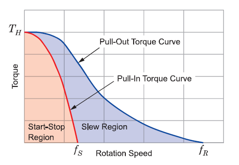
Reading a Speed-Torque Curve
- Holding Torque
The amount of torque the motor produces at rest when it has rated current flowing through its windings. - Start/Stop Region
The values at which the motor can start, stop, or reverse instantly. - Pull-In Torque
The values of torque and speed that the motor can start, stop, or reverse in synchronism with the input pulses. - Pullout Torque
The values of torque and speed that motor can run in synchronism with the input phases. The maximum values the motor can provide without stalling. - Maximum Starting Speed
The maximum speed the motor can start at measured with no load. - Maximum Running Speed
The fastest speed the motor will run at, measured with no load.
In order to operate in the region between the pull-in and pullout, the motor must first start in the start/stop region. The pulse rate is then increased until the desired speed is reached. To stop, the motor speed is then reduced until it is below the pull-in torque curve.
Torque is proportional to the current and the number of turns of wire. If we want to increase the torque by 20%, we should increase the current by about 20%. Similarly, if we want to decrease the torque by 50%, reduce the current by 50%.
Because of magnetic saturation, there is no advantage to increasing the current to more than 2 times rated current. At that point the increase in current won't increase the torque. At about 10 times rated current you run the risk of demagnetizing the rotor.
All of our motors have Class B insulation and can withstand 130°C before the insulation degrades. If we allow a 30° temperature differential from the inside to the outside, the case should not go above 100°C.
Inductance affects high speed torque. Inductance is the reason why motors don't have a high degree of torque out to infinity. Each motor winding has a certain value of inductance and resistance. Inductance in henrys, divided by resistance in ohms, gives us a value of seconds. This amount of seconds (time constant) is the amount of time it takes the coil to charge up to 63% of its rated value. If the motor is rated for 1 amp, after 1 time constant, the coil will be at 0.63 amps. After about 4 or 5 time constants the coil will be up to 1 amps. Since torque is proportional to current, if the current is only charged up to 63%, the motor will only have about 63% of its torque after 1 time constant.
At low speeds, this is not a problem. The current can get in and out of the coils fast enough, so the motor has rated torque. At high speeds, however, the current can't get in fast enough before the next phase is switched. Torque is reduced.
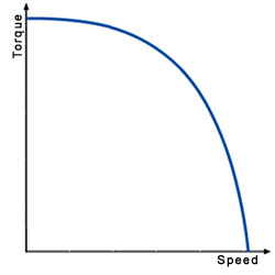
Driver voltage plays a large part in high speed performance. The higher the ratio of drive voltage to motor voltage, the better the high speed performance. High voltages force the current into the windings at a faster rate than the 63% mentioned above.
Vibration
When a stepper motor makes a move from one step to the next, the rotor doesn't immediately stop. the rotor actually passes the final position, is drawn back, passes the final in the opposite direction and continues to move back and forth until it finally comes to a rest (see interactive diagram below). We call this "ringing" and it occurs every single step the motor takes. Similar to a bungee cord, the momentum carries the rotor past its stop point, it then "bounces" back and forth until finally coming to rest. In most cases, however, the motor is commanded to move to the next step before it comes to a rest.
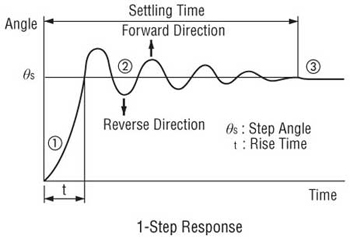
The graphs below show the ringing under different load conditions. Unloaded, the motor exhibits a lot of ringing. A lot of ringing means a lot of vibration. The motor will often stall if it is unloaded or lightly loaded because the vibration is so high it will lose synchronism. When testing a stepper motor always be sure to add a load.
The other two graphs show the motor with a load. Loading a motor properly will smooth out its performance. The load should require between 30% to 70% of the torque the motor can produce, and the ratio of load inertia to rotor inertia should be between 1:1 and 10:1. For shorter, quicker moves, the ratio should be closer to 1:1 to 3:1.
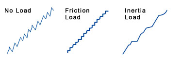
ORIENTAL MOTOR application specialist and engineers can assist in proper sizing.
The motor will exhibit much wilder vibrations when the input pulse frequency matches the natural frequency of the motor. This is called resonance and usually occurs around 200Hz. In resonance, the overshooting and undershooting become much greater and the chance of missing steps is much higher. The resonance changes depending on the load inertia, but it is usually around 200Hz.
2-Phase stepper motors can only miss steps in groups of four. If you are missing steps in multiples of four, the vibration is causing a loss of synchronism, or the load is too great. If the missed steps are not a multiple of four, there's a good chance the wrong number of pulses or electrical noise is causing the problems.
There are a number of ways to get around resonance. The easiest way is to avoid that speed altogether. 200 Hz is not tremendously fast, for a 2-phase motor that is 60 rpm. Most motors have a maximum starting speed around 1000 pps or so. So in most cases you can start the motor at a higher speed than the resonant speed.
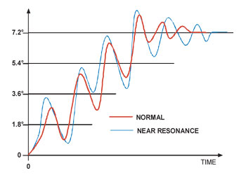
If you have to start at a speed below the resonant speed, accelerate through the resonant range quickly.
Another solution is to make the step angle smaller. The motor will always overshoot and undershoot more for bigger step angles. If the motor doesn't have to travel far, it will not build up enough force (torque) to overshoot a large amount. Anytime the step angle is made smaller, the motor will not vibrate as much. This is why half-stepping and microstepping systems are so effective at reducing vibration.
Make sure the motor is sized properly to the load. By choosing the proper motor you can improve performance.
Dampers are also available. Dampers fit on the back shaft of a motor and absorb some of the vibrational energy. They'll often smooth out a vibrating motor inexpensively.
5-Phase Stepper Motors
A relatively new technology in stepper motors is 5-phase. The most obvious difference between 2-phase and 5-phase (see interactive diagram below) is the number of stator poles. While 2-phase motors have 8 poles, 4 per phase, the 5-phase motor has 10 poles, 2 per phase. The rotor is the same as that of a 2-phase motor.
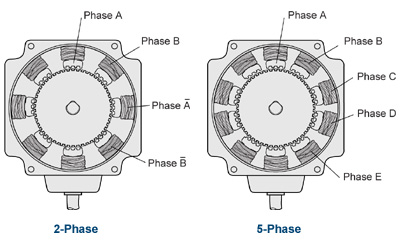
While the 2-phase motor moves 1/4 tooth pitch each phase. The 5-phase, because of its construction, moves 1/10 of a tooth pitch. Since the pitch is still 7.2°, the step angle is 0.72°. Simply based on construction, the resolution of the 5-phase has 500 steps per revolution versus the 2-phase with 200 steps per revolution. The 5-phase offers a resolution 2.5 times better than that of the 2-phase.
With a higher resolution you get a smaller step angle, which in turn reduces vibration. Since the step angle of the 5-phase is 2.5 times smaller than the 2-phase the ringing, vibrations, are much lower. In both 2-phase and 5-phase, the rotor must overshoot or undershoot more than 3.6° to miss steps. Because the step angle of the 5-phase is only 0.72°, it is almost impossible for the motor to overshoot or undershoot by 3.6°. The chances of losing synchronism with a 5-phase stepper motor are very low.
Drive Methods
There are four different drive methods for stepper motors:
- Wave Drive (Full Step)
- 2 Phases On (Full Step)
- 1-2 Phases On (Half Step)
- Microstep
Wave Drive
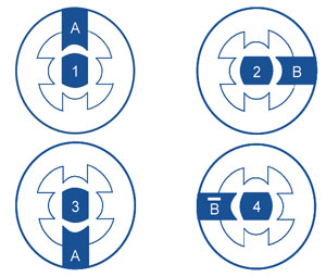
In the diagram below, the wave drive method has been simplified to better illustrate the theory. In the illustration each 90° turn is representing 1.8° of rotor rotation in an actual motor.
In the wave drive method (also called the 1-phase ON method), only one phase is turned on at a time. When we energize the A phase a a south pole, it attracts the north pole of the rotor. We turn off A and turn on B, the rotor rotates 90° (1.8°) and so on. Each time only one phase is energized.
The wave drive has a four step electrical sequence to rotate the motor.
2 Phases On
In the "2 phase on" method, two phases are always energized.
Once again in the illustration below, every 90° represents a 1.8° rotation. If both phases A and B are energized as south poles, the north pole of the rotor will be equally attracted to both poles and line up directly in the middle. In sequence as the phases are energized, the rotor will rotate to line up between the two energized poles.
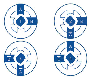
The "2 phase on" method has a four step electrical sequence to rotate the motor.
ORIENTAL MOTOR's standard 2-phase and 2-phase M type motors use the "2 phase on" method.
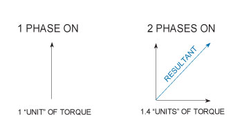
What advantage does the "2 phase on" method have over the "1 phase on" method? The answer is torque. In the "1 phase on" method, only one phase is turned on at a time, so we have one unit of torque acting on the rotor. In the "2 phase on" method, we have two units of torque acting on the rotor, 1 at the 12 o'clock position and 1 at the 3 o'clock position. If we add those two torque vectors together, we get a resultant at 45° and the magnitude is 41.4% greater. By using the "2 phase on" method we can get the same step angle as the "1 phase on" method, but with 41% more torque.
Five phase motors are a bit different. Rather than using the "two phase on" method, we use the "four phase on" method. Each time we turn on 4 of the phases and the motor takes a step.
The five phase motor goes through a 10 step electrical sequence.
1-2 Phases On (Half Step)
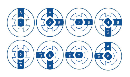
The "1-2 phase on" method or half stepping combine the two previous methods. In this case, we energize the A phase. The rotor lines up. At this point we keep the A phase on and energize the B phase. Now the rotor is equally attracted to both an lines up in the middle. The rotor has rotated 45° (0.9°). Now we turn off phase A but leave on phase B. The motor makes another step. And so on and so forth. By alternating between one phase on and two phases on, we have cut the step angle in half. Remember that with a smaller step angle, the vibration is reduced.
(For a 5-phase motor, we alternate between 4 phases and 5 phases on.)
The half step mode has an eight step electrical sequence. For five phase motor in "4-5 phase on" method the motor goes through a 20 step electrical sequence.
Microstep
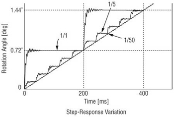
Microstepping is a way to make small steps even smaller. The smaller the step, the higher the resolution and the better the vibration characteristics. In microstepping, a phase is not fully on or fully off. It is partially on. Sine waves are applied to both phase A and phase B, 90° apart (0.9° in a five phase stepper motor).
When the maximum power is in phase A, phase B is at zero. The rotor will line up with phase A. As the current to phase A decreases, it is increasing to phase B. The rotor will take tiny steps toward phase B until phase B is at its max and phase A is at zero. The process continues around the other phases and we have microstepping.
There are some problems associated with microstepping, mostly accuracy and torque. Because the phases are only phases are only partially energized, the motor torque is reduced, usually by about 30%. Also because the torque differential between steps is so small, the motor sometimes cannot overcome the load. In those cases the motor may be commanded to move 10 steps before it actually starts to move. In many cases it is necessary to close the loop with encoders which add to the price.
Stepper Motor Systems
- Open Loop Systems
- Closed Loop Systems
- Servo Systems
Open Loop
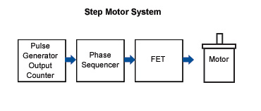
Stepper motors are designed as an open loop system. A pulse generator sends out pulses to the phase sequencing circuit. The phase sequencer determines which phases need to be turned off or on as described in the full step and half step information. The sequencer controls the big power FETs which then turns the motor.
With an open loop system, however, there is no position verification and no way to know if the motor made its commanded move.
Closed Loop
The most popular method of closing the loop is adding an encoder on the back shaft of a double shafted motor. The encoder is made up of a thin disc with lines on it. The disc passes between a transmitter and a receiver. Each time a line comes between the two, a pulse is output on the signal lines. These pulses are fed back to the controller which keeps count of them. Usually, at the end of the move the controller compares the number of pulses sent to the driver with the number of encoder pulses sent back. A routine is usually written that if the two numbers are different, the difference is then made up. If the numbers are the same, no error has occurred and motion continues.
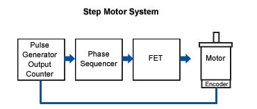
This method has two drawbacks: cost (and complexity) and response. The additional cost of the encoder, along with the increase in sophistication of the controller add cost to the system. Also, since the correction (if any) is done at the end of the move, additional time could be added into the system.
Servo System
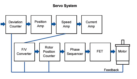
Another option is a servo system. A servo system is typically a low pole count motor that gives high speed but has no inherent positioning capability. To make it a position device, feedback is required, usually and encoder or resolver, and control loops. The servo is essentially turned on and off until the resolver count reaches a certain point. Therefore, the servo works based on error. For example, the servo is commanded to move 100 revs. The resolver count reads zero and the motor is turned on. When the resolver count reaches 100 revs, the motor is turned off. If the position deflects, the motor is turned back on to bring it back to position. How the servo responds to error depends on a gain setting. If the gain setting is high, the motor will respond very quickly to any changes in error. If the gain setting is low, the motor will not respond as quickly to changes in error. Any time gain settings are involved though, time delays are introduced into the motion control system.
AlphaStep Closed Loop Stepper Motor Systems
AlphaStep is Oriental Motor's revolutionary stepper motor product. The AlphaStep has a built-in resolver that provides position feedback. At all points in time we know where the rotor is.
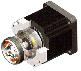
The AlphaStep driver has an input counter. All pulses that go to the drive are counted. The resolver feedback goes to the rotor position counter. Any deviation is present in the deviation counter. Normally the motor runs open loop. We make torque vectors and the motor follows. If the deviation counter shows anything greater than ± 1.8°, the phase sequencer turns on the torque vector at the high part of the torque displacement curve, generating maximum torque to bring the rotor back into synchronism. If the motor is off by several steps, the sequencer energizes several torque vectors on the high part of the torque displacement curve. The driver can handle an overload for up to 5 seconds. If it cannot bring the motor back into synchronism within 5 seconds, the driver will fault and send out an alarm.
The great feature of the AlphaStep is that it makes corrections for missed steps on the fly. It doesn't wait until the end of the move to make corrections. Once the rotor is back within 1.8°, the driver goes back into the open loop mode and sends out the proper phase energizations.
The graph below shows the torque displacement curve and when the unit is in open or closed loop mode. The torque displacement curve is the torque generated by one phase. It products a maximum torque when the rotor teeth are displaced by 1.8°. A motor can only mis a step if it overshoots by more than 3.6°. Since the driver takes control of the torque vector when it misses by 1.8°, there is no way the motor can miss steps except if it is overloaded for more than 5 seconds.
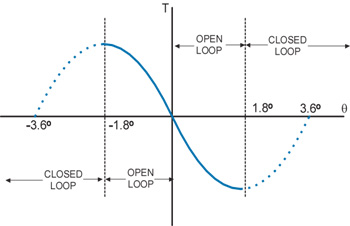
Many people think that the step accuracy of the AlphaStep is ± 1.8°. The step accuracy of the AlphaStep is 5 arc minutes (0.083°). The driver controls the torque vectors outside of 1.8°. Once inside 1.8°, the rotor teeth will line up with the torque vector that's being generated. AlphaStep makes sure the proper tooth is lining up with the torque vector.
AlphaStep is available in many versions. ORIENTAL MOTOR offers round shaft and geared versions with several gear ratios to increase resolution and torque or to reduce the reflected inertia. Almost all versions can be fitted with a fail-safe magnetic brake. ORIENTAL MOTOR also has a 24 VDC version called the ASC series.
Conclusion
In summary, stepper motors are excellent for positioning applications. Stepper motors can be precisely controlled in terms of both distance and speed simply by varying the number of pulses and their frequency. Their high pole count gives them accuracy while at the same time they run open loop. If sized properly for the application, a stepper motor will never miss a step. And because they don't need positional feedback, they are very cost effective.
